


Marina AC power is safe and convenient, as long as you know how to install and manage it properly aboard your yacht. Duncan Kent offers expert advice
Not long ago, having any form of mains AC (alternating current) on board a small to medium sized leisure boat was rare. But now, having shore power in a yacht is increasingly standard practise.
A 240V facility seems to be a prerequisite of any marina berth, supplying enough power to run heaters, kettles, water heaters, microwaves and more. In fact, it’s becoming increasingly rare to find any boat relying on its own power resources whilst marina-based, even when they’re paying for it on a meter.
However, this new abundance of AC power comes with the problem of how to safely handle and manage it aboard a yacht. It’s important to remember that AC can be a killer, particularly when you’re floating on a highly efficient conductor such as salt water. It’s vital, therefore, that great care should be taken over an onboard AC installation, which, for many, will mean calling in professional assistance.

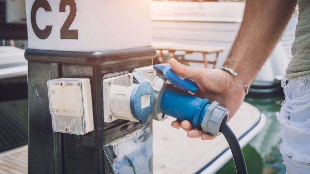
Shore power cables have become essential cruising kit
Any AC installation starts with the shore power cable, plugs and onboard sockets.
In UK marinas and boatyards, the connection points are now pretty much standardised so it’s possible to buy a kit with a pre-terminated cable and a suitable socket for the boat. Despite having a water-resistant gasket and sprung, waterproof cover, the boat socket should ideally be mounted in a relatively protected area.
Inside the boat, the current carrying capacity of the cable running between the shore power inlet socket and the consumer unit (CU) must be as high, or higher than the maximum supply current, and no more than 3m long. Although most UK pontoon outlets are limited to 16A, it’s advisable to install a 30A, 3-core cable to the CU.
Cable to match these ratings is readily available from most marine electrical suppliers, but it needs to be the flexible, multi-strand, and preferably tinned conductor type, not the solid copper conductor intended for domestic wiring. This is so the conductor will not fracture when subjected to vibration or flexing.

A galvanic isolator should be installed
Installing isolators
It is highly recommended you install a galvanic isolator (GI) into the earth circuit on the shore side of the CU, which will allow high voltage AC currents to be conducted to earth, but in the event of a problem will stop any DC leakage (up to 1.4V) from flowing.
An alternative to a GI is an isolation transformer, which is by far the best way to eliminate the risk of stray currents and other problems, as they effectively leave the boat totally isolated from the shore connection while still creating a 230V AC supply. However, isolation transformers are expensive, bulky and heavy, so are rarely fitted to small craft.
If the cable is to be fed through a cockpit locker or similarly vulnerable space it should run through protective trunking. Plastic mini trunking epoxied onto the hull side is very effective and allows you to add, inspect or remove cables easily later on.
It’s also important to be able to check and correct the polarity of the supply. Polarity detectors are easy to find; in fact some CUs or AC panels now incorporate them, but actually changing the polarity over to what it should be requires a switch or polarity reversal cable inserted into the shore power lead.
Some protection against polarity reversal is included if the correct CU is installed, as it will have double-pole circuit breakers to ensure that whichever conductor is live is always disconnected.

Signs of damage on an overheated shore power cable
Safety and circuit protection
A suitable consumer unit (CU) must be installed to provide protection against electric shock hazards. It must meet the latest regulations for mobile installations, which means you can’t just buy a domestic unit or one designed for sheds and garages.
By law, all AC installations must have a Residual Current Device (RCD), also known as a Ground Fault Circuit Interrupter (GFCI), as the first line of protection in any AC circuit. The correct RCD for mobile installations is an A-type, as opposed to the domestic AC-type, and it should also contain double-pole Mini Circuit Breakers (MCB), not the more common single-pole breakers.
An RCD is a two-pole circuit breaker used to protect circuits and people from current leakage to an earthed source. Under normal operation, the current flowing into the appliance via the live conductor should be identical to that returning via the neutral wire.
If it isn’t, then some of the current must be leaking out from the appliance via the earth wire, or through some other conductor (such as a human being), in which case the RCD will trip.
You should also fit a suitably rated MCB for the AC socket outlets, and separate dedicated MCBs for heavy load devices such as an electric cooker.
When planning the system, calculate the total AC current you’re ever likely to draw simultaneously (bearing in mind most shore power supplies are 16A), and the maximum load on each branch off the CU, in order to select the correctly rated circuit breakers. Remember, an MCB is there to protect the cable, not the appliance, which should have its own built-in fuse or trip.

An RCD will trip if an appliance is producing a natural earth leakage
Nuisance tripping
An RCD can trip for no apparent reason. This can either be caused by the system having two neutral-to-earth (MEN) links at different potentials (centre tapped inverters for instance), or some appliance that is producing a small amount of natural earth leakage.
Any AC power source, be it grid, generator or inverter, always has to have a MEN link. In the case of the grid, this is usually done at the sub-station, but it can be done additionally at a point of distribution such as a meter board.
With a generator, the link is pre-wired internally, and the same goes for many inverters. With inverter/charger combis, it’s more complex as the link is needed when inverting but not when charging, as that is provided by the grid or generator. So, combi inverters will usually have a relay that switches between the two.

A UK mains electric plug showing the correct wiring
Distribution and wiring
Mains 230V AC systems must have a separate switch panel to the DC wiring to avoid any risk of confusion or leakage across to the DC system. Some marine specific AC distribution panels have circuit protection built in, however, it’s important to ensure any circuit breakers supplied are double-pole and the trip-free type that cannot be held in the ‘on’ position in the event of it tripping out.
Regulations also state that the panel must be clearly marked with a ‘240V AC – risk of death’ warning sign, stating that the shore power cable should be disconnected before accessing the wiring. Furthermore, the panel must require a tool to access the wiring at the rear, and all the AC terminations should be protected by a screwed-down cover carrying an additional warning label.
AC cabling should ideally be kept separate from the DC wiring and not bundled together inside a conduit, although the regulations state this is acceptable provided the cables have a partition between them.
Keeping them separate is primarily for safety reasons, but also because the DC side might induce an additional current within the AC cable that can cause interference with sensitive electronic equipment.
Cables not inside conduit should be supported with cleats every 400mm, and clearly marked as AC conductors at regular intervals.
Normal domestic AC sockets may be used around the boat (provided they have an earth terminal), although it’s preferable to use the type with a sprung protective cover to avoid any splashes getting into the sockets.

Take care when connecting mains electricity in a marina – damp fingers can kill
Connections and terminations
As with DC wiring, how well the conductors are terminated dictates how efficiently and safely the whole AC system will operate.
Only ring terminals that correctly match the studs, or flanged spade connectors should be used as these will physically resist being pulled off. Ideally, use heat-seal terminals that have adhesive incorporated into the stem. Alternatively, if using standard crimp terminals, heat shrink should be placed around each joint and shrunk on tightly.
This not only seals the joint from moist air, but also provides additional strain relief on the wire.
It’s a good idea to use write-on identification heat shrink above the connector to indicate which wire does what. It is debatable whether it’s better to actually state what the wire does, or where it leads to, rather than using a numbering system whose index is highly likely to get lost at some point.
Article continues below…

The technical challenges of recycling batteries
Batteries are in many ways anathema to sailors. They are heavy, finicky things, whose performance wanes with time, requiring an…

Sail handling systems: push button sailing
Electric sail handling systems are not just for maxi yachts. Sam Fortescue looks at how push button sailing is filtering…
Nylon cable ties are cheap and much better for keeping cables together than insulating tape, which often goes gooey and unpeels over time. You can also get self-adhesive cable tie mounts to keep the wiring organised and tidy.
Use rubberised grommets when feeding cable through bulkheads and panel holes to protect the insulation. Alternatively, lengths of flexible grommet are available for trimming round large, or non-round apertures.
Finally, always allow enough cable at the back of the distribution panel in order to hinge it down or place it on a flat surface to work on.
Also, drip loops should be incorporated into any loom before it reaches the panel, consumer unit or any other electrical appliance.
It can’t be emphasised enough that AC (even the output of a small inverter) can kill someone who sticks damp fingers in the wrong place, so a clear distinction between AC and DC outlets must be made and the appropriate label applied.
Connections inside a typical 10kVA 230V transfer switch
Multiple AC sources
In cases where there is more than one source of AC (grid, generator and/or inverter), never allowing more than one source to be applied to the same circuit simultaneously is of critical importance. Different supplies should always be fed directly into a manual or automatic multi-way transfer switch that can totally isolate the different sources from each other. Connecting two or more differently phased AC supplies together is likely to cause a serious fire.
Automatic relay-switched control boxes are available that can disconnect one supply (inverter, say) when it detects another (the grid maybe) is present, but if you are in any doubt about how to interconnect more than one supply, you are seriously advised to seek advice from a professional electrician.
Tips to install shore power on a yacht
Do
- Buy the right capacity and type of cable for each job
- Keep the cable from inlet to RCD as short as possible (max 3m)
- Segregate all AC wiring from the DC and install separate switch panels
- Clearly mark all AC devices and cables with warning labels
- Protect and support cables in open areas or engine compartments
- Fit an overload circuit breaker for each high-current device
- Fit a polarity reversal indicator and changeover switch
Don’t
- Connect any device to the incoming supply (other than a GI) before the RCD
- Use cheap terminal blocks as connectors
- Install AC cables in the bilges
- Use solder on any cable terminals
Enjoyed reading this?
A subscription to Yachting Monthly magazine costs around 40% less than the cover price.
Print and digital editions are available through Magazines Direct – where you can also find the latest deals.
YM is packed with information to help you get the most from your time on the water.
-
-
- Take your seamanship to the next level with tips, advice and skills from our experts
- Impartial in-depth reviews of the latest yachts and equipment
- Cruising guides to help you reach those dream destinations
-
Follow us on Facebook, Twitter and Instagram.